Mechanical engineering
Standard press, heat press, punching press, punching tool carrier…
Mechanical engineering, performance and foaming process
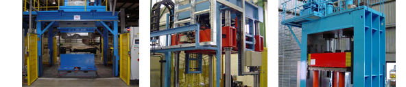
In classical mechanical engineering, we can offer you a wide range of pressure transducers which can be delivered as standard press, heat press, punching press, punching tool carrier or as a combination. The closing forces range from 200 kN to 3000 kN. In terms of performance, box, four column as well as gantry concepts are available. The drive can be realized according to the downstroke, upstroke or double stroke concept. In the foaming process we work with standardized swivel foaming mold carrier systems with opening angles of 90 to 135 °.
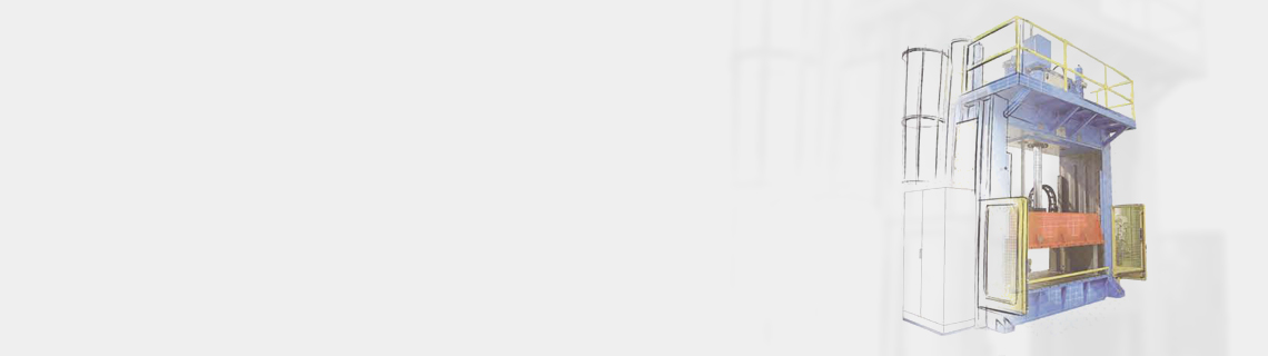
Downstroke pressure transducer in frame construction
MThe machine frame and the vertical lifting table are executed as a box design welded-steel construction. The base frame is aligned and fixed at the machine site by means of leveling and anchoring screws. The guide elements are each equipped with a highly measured chrome-plated, solid round guide as well as a highly measured chrome-plated, solid flat guide. The guiding concept is stabilized by means of a 2-wave synchronizing device. The lifting table movement is effected by one or more hydraulic cylinders. Each machine is usually equipped with a standard stroke of 1,300 mm and a tool block size of 700 mm, resulting in an opening width of 2,000 mm. Deviations from this standard are possible at any time at customer’s request.
Possible closing forces: 500 kN, 750 kN, 1.000 kN, 1.600 kN, 2.000 kN, 3.000 kN
Possible table sizes in mm: 2.000 x 1.300, 2.450 x 1.300, 2.600 x 1.300, 2.200 x 1.500, 2.400 x 1.500, 3.000 x 1.500
… further technical data:
- Deflection: 0,2 mm / m at 2/3 surface loadg
- Protection: light protection on the front, Sitema – clamping head, perforated plate covering all around
- Control: Siematic S7 or Allen Bradley
- Tool attachment: T-slots M20, in 250 mm distance over machine width
Additional equipment / Options:
- Thermo oil heating plates on top / at the bottom
- Multiple punching circle
- Double-sided operability
- Hydraulic quick-release
- Tool changing device
- Remote maintenance option
Downstroke pressure transducer four column construction
The machine base, traverse and vertical lifting table are executed as a box design welded steel construction, the lower part is aligned and fixed by means of leveling and anchoring screws at the machine site. The guide elements are made of 4 highly measured chrome-plated, solid round guides. The lifting table movement is effected by one or more hydraulic cylinders. Each machine is usually equipped with a standard stroke of 1,500 mm and a tool block size of 500 mm, resulting in an opening width of 2,000 mm. Deviations from this standard are possible at any time at customer’s request.
Possible closing forces: 800 kN, 1.300 kN, 3.000 kN
Possible table sizes in mm: 2.000 x 1.300, 2.200 x 1.500, 2.750 x 1.600
… further technical data:
- Deflection: 0,2 mm / m at 2/3 surface load
- Protection: light protection on the front, Sitema – clamping head, perforated plate covering all around
- Control: Siematic S7 or Allen Bradley
- Tool attachment: T-slots M20, in 250 mm distance over machine width
Additional equipment / Options:
- Thermo oil heating plates on top / at the bottom
- Multiple punching circle
- Double-sided operability
- Hydraulic quick-release
- Tool changing device
- Remote maintenance option
Upstroke pressure transducer in four column construction
The lower, upper and lifting tables are manufactured as a box design welded steel construction. The lower part is aligned and fixed by means of levelling and anchoring screws at the machine site. The guide elements are made of 4 highly measured chrome-plated, solid round guides. The guiding concept is stabilized by means of a 2-wave synchronizing device. The lifting table movement is effected by 4 hydraulic cylinders of various sizes, depending on the closing force requirement. Each machine is generally equipped with a standard stroke of 1,400 mm and a tool block size of 600 mm, resulting in an opening width of 2,000 mm. Deviations from this standard are possible at any time at customer’s request.
Possible closing forces:500 kN, 1.000 kN
Possible table sizes in mm: 1.750 x 1.300, 2.450 x 1.500
… further technical data:
- Deflection: 0,2 mm / m at 2/3 surface load
- Protection: light protection on the front, Sitema – clamping head, perforated plate covering all around
- Control: Siematic S7 or Allen Bradley
- Tool attachment: T-slots M20, in 250 mm distance over machine width
Additional equipment / Options:
- Thermo oil heating plates on top/ at the bottom
- Multiple punching circle
- Double-sided operability
- Hydraulic quick-release
- Tool changing device
- Remote maintenance option
Gantry presses
Accessible downstroke or upstroke frame presses are generally called gantry presses. The frame parts are a box design welded steel construction as well as the respective lifting table. The frame is aligned and fixed by means of levelling and anchoring screws at the machine site. A rack pinion linked by 4 waves is used as a guide concept (synchronization functionality). The lifting movement is effected by 2 or 4 hydraulic cylinders of various sizes, depending on the closing force requirement. Each machine is generally equipped with a standard stroke of 1,300 mm and a tool block size of 700 mm, resulting in an opening width of 2,000 mm. Deviations from this standard are possible at any time at customer’s request. These machines are used for the backfoaming and the manual forming.
Possible closing forces: 200 kN, 300 kN, 500 kN
Possible table sizes in mm: 2.400 x 1.800, 2.500 x 1.700, 3.200 x 1.900
… further technical data:
- Deflection: 0,2 mm / m at 2/3 surface load
- Protection: light protection on the front, Sitema – clamping head, indoor scanner, perforated plate covering all around
- Control: Siematic S7 or Allen Bradley
- Tool attachment: T-slots M20, in 250 mm distance over machine width
Additional equipment / Options:
- Double-sided operability
- Hydraulic quick-release
- Tool changing device
- Remote maintenance option
Foam mould carrier
A foam mould carrier serves as a dimensionally stable and closing unit for the installation and operation of steel and aluminum tools in which PUR foam parts are produced for acoustic insulation purposes. The foam parts essentially consist of two components which react with one another within the tool and harden. The reaction forces occurring within the tool must be absorbed by the mold carrier.
As a rule, our foam mould carriers are designed as a solid welded steel construction and hydraulically driven. They are equipped with a pneumatically or hydraulically operating lifting membrane in the lower part of the frame (stroke can be selected within limits) which can be carried out selectively with and without a synchronization system. These foam mould carriers are available with different opening angles (<90 ° to> 180 °) and swivel systems according to the customer requirements. Such a system consists of the hydraulic basic supply, a central control unit and 1 – max. 8 foam mould carrierunits, each of which is equipped with a local supply unit.
Electromotor driven units on request …!
… would you like further information or do you need an offer? -> … please send us your inquiry!